
This time we publicize a lightly 🙂 digestible story about the repair of our DR-1x repeater from Yaesu that is used by the Dutch Hobbyscoop foundation for the PI1NOS repeater system. A few weeks ago we came to the insight that the repeater was suddenly no longer approachable, not only via the RF path but also via our remote control the repeater could not be reached. The 15A fuse appeared to be defective on the spot and replacement didn’t solve our problem, the new fuse blew instantly as well…
The defect …
TX part
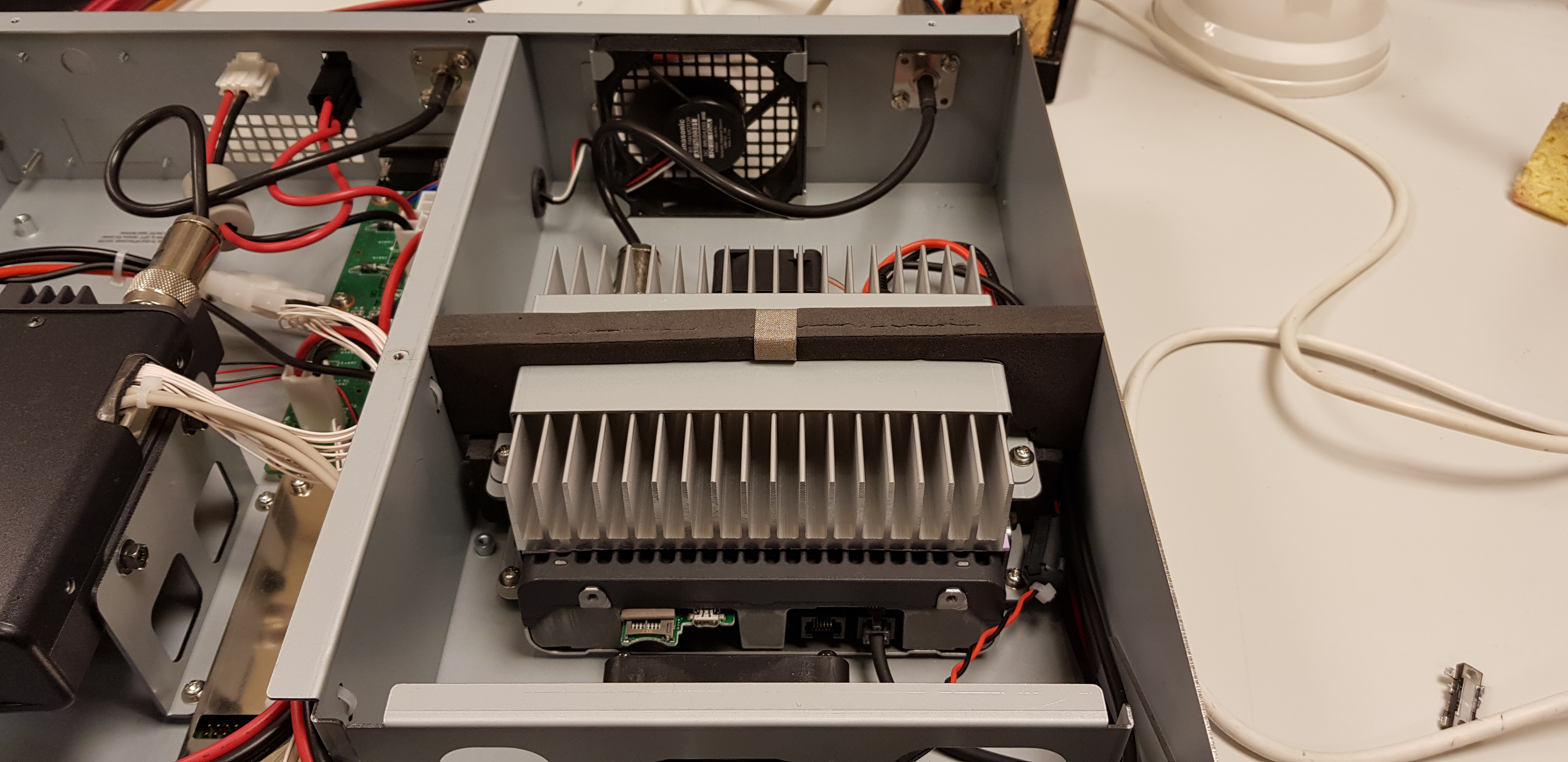
The DR-1x repeater is in fact nothing more than two Yaesu FTM400 transceivers in a modified version that are positioned together with some control logic in a 19 Inch enclosure. The transmitter is equipped with an extra cooling block on top of the original cooling chassis with the aid of a silicone heat conductor. A look inside the repeater at an earlier stage already raised the question whether the contrapsion would be capable of long lasting transmissions without malfunctioning; Yaesu has tried to create a “forced air tunnel” with the aid of two fans to keep things nice and cool, however, the implementation clearly has its limitations, unfortunately that has been proven many times now. FTM400 owners regularly experience problems with the power amp as well, when used at UHF at 50 Watts.
DR-1x from a friend, less fortunate then our units…
Before PI1NOS was used in its current configuration, we have talked with a well-known repairer of radio equipment for radio amateurs in NL, PA0LMD (Leo Duursma). Because we already received different reports from other DR-1x users that these repeaters become defective rather easily, we have asked him if this problem is known. Leo reported that Yaesu has prescribed a modification for this setup in the form of a modified transmitter chassis. The original chassis was completely closed; no air could flow over the PCB. With 50 Watt transmission power on UHF certain components become quite warm so that even PCBs were completely burned, we do not want that at Hobbyscoop. The new housing was ordered via Leo for all our fusion repeaters and that’s how things have been put to use, assuming all would be fine.
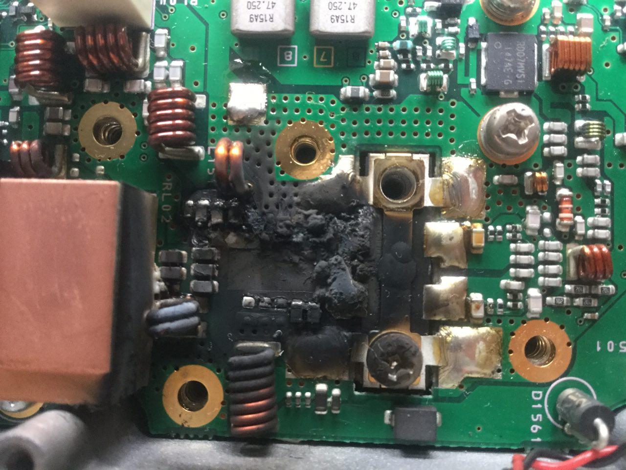
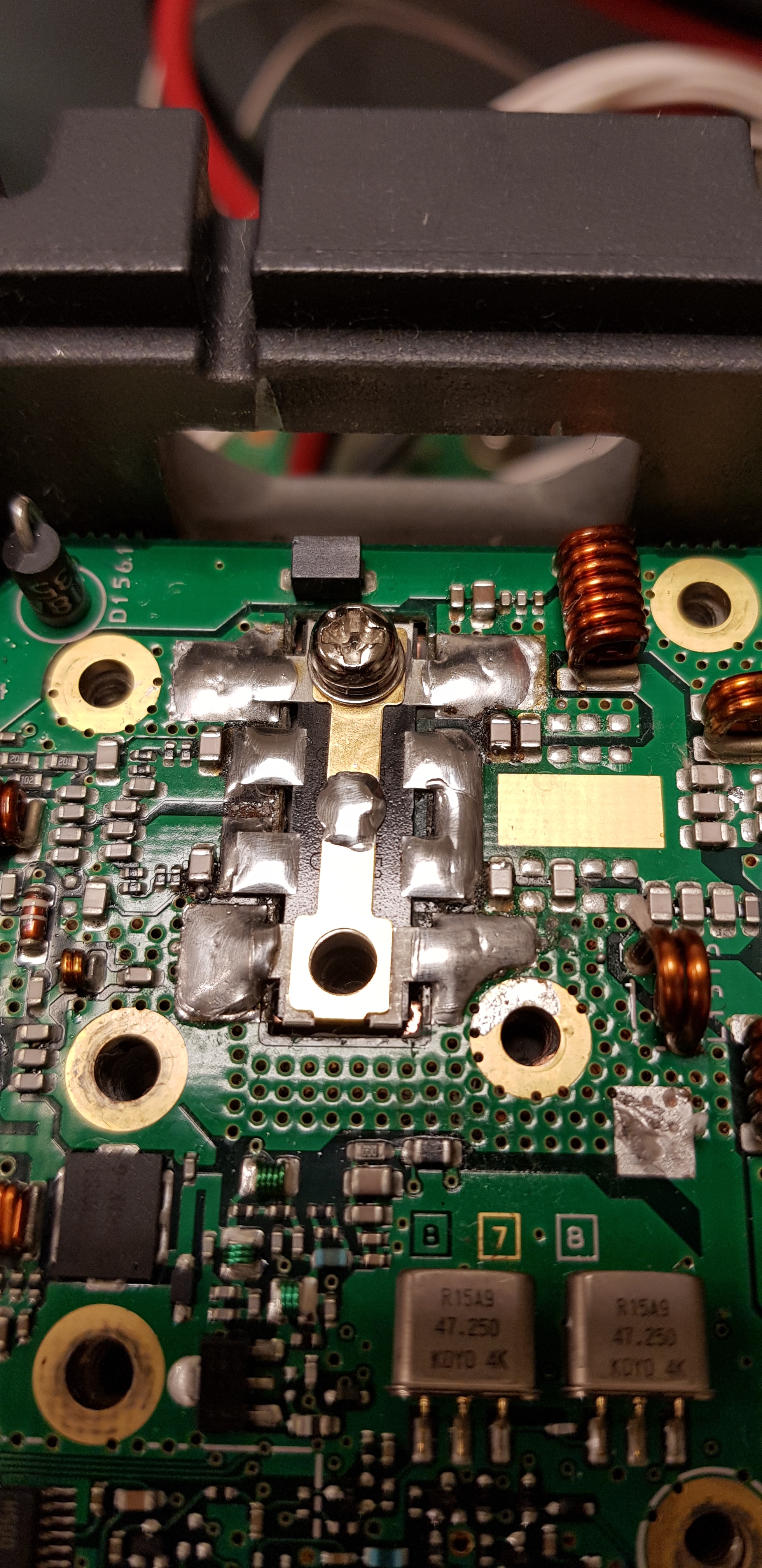
Now that the repeater is defective, we suspected problems with the power amplifier. To test this, the drain of the power fet (a Mitsubischi RD70-HUF2) has been de-soldered. The dynamic short-circuit immediately abolished, clearly concluding a defective power fet. The big question, however, is why this fet has failed in the given circumstance. The typical output power of this fet amounts to 75 Watts on UHF; the 50 watts of the DR-1x / FTM400 should not actually be a problem.
Minor calculations
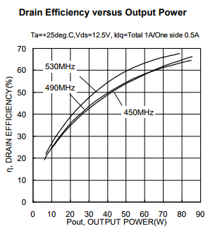 Mitsubishi specifies a drain efficiency of 64% at 530MHz for this fet type. The datasheet however says that at 450MHz at 50Watt output power an efficiency of a tight 53% is reached. At 50 watts output power the total power consumed is theoretically about 95 watts; 45 Watts are then converted into heat. The absorbed current through the amp would then have to be about 7A. Measurements, however, resulted in a current of more than 8.5A, which means that at 50 watts from about 115 watts is dissipated, that is significantly more heat than we expected, namely 65 watts of heat. The higher current can be explained well: Yaesu has designed the FTM400 and DR-1x as a dual-band transceiver with a single power fet for all frequency ranges. The RD70-HUF2 suits perfectly for this purpose. Design compromises must however be made to allow operation on 2m and 70cm with one amplifier…
The drain output impedance at 450MHz (which we take as the starting point) is 0.87 + J1.0 Ohm, while at VHF it is about 4.9 + J1.6 Ohm. This means that, without having to stick to a large series of switchable components for VHF and UHF, it is necessary to cut down on some performance parameters. This does not have to be a problem, as long as there are sufficient provisions to adequately drain the excess heat, and that is where the problem lies with these transceivers. We already learned from Leo that FTM400s are regularly subject to repair, especially if they are used at high power at UHF. Now an FTM400 is meant for home use. Very long-term transmissions on high power do not occur that often. However a repeater should, in our opinion, be able to transmit at full power at a duty cycle of 100%. The prescribed modification of Yaesu is therefore not conclusive.
Cooling
I have briefly considered to optimize the transceiver for UHF operation only. Ultimately it was decided not to do this because the set on the one hand can no longer be used at 2 meters but at the same time there is also the idea that, despite a lesser efficiency, an optimal cooling system still must exist; This clearly does not seem to be the case. In the meantime, a new RD70-HUF2 has been ordered that comes directly from Yaesu. In addition, the cooling system has been extensively evaluated in preparation for the repair.
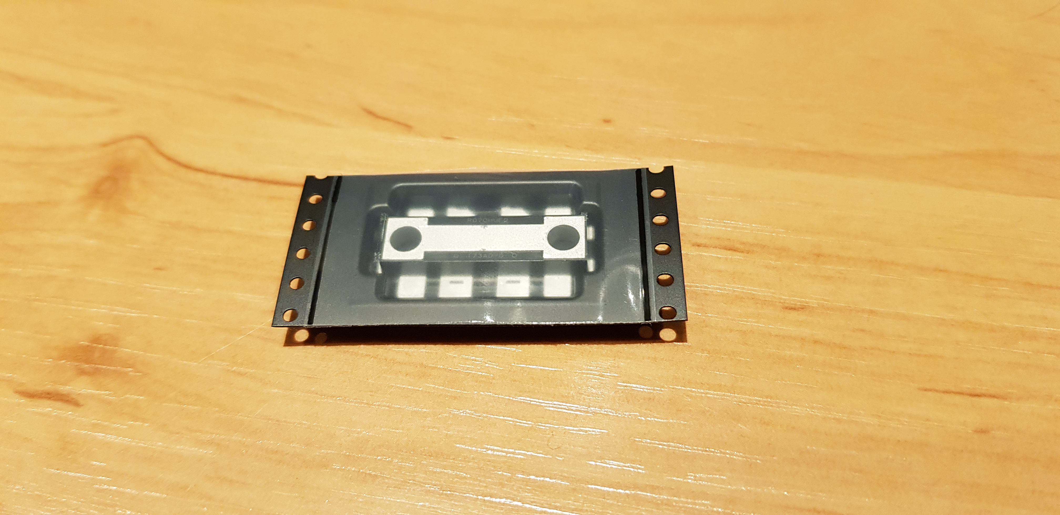
New RD-70-HUF2, a rather small device
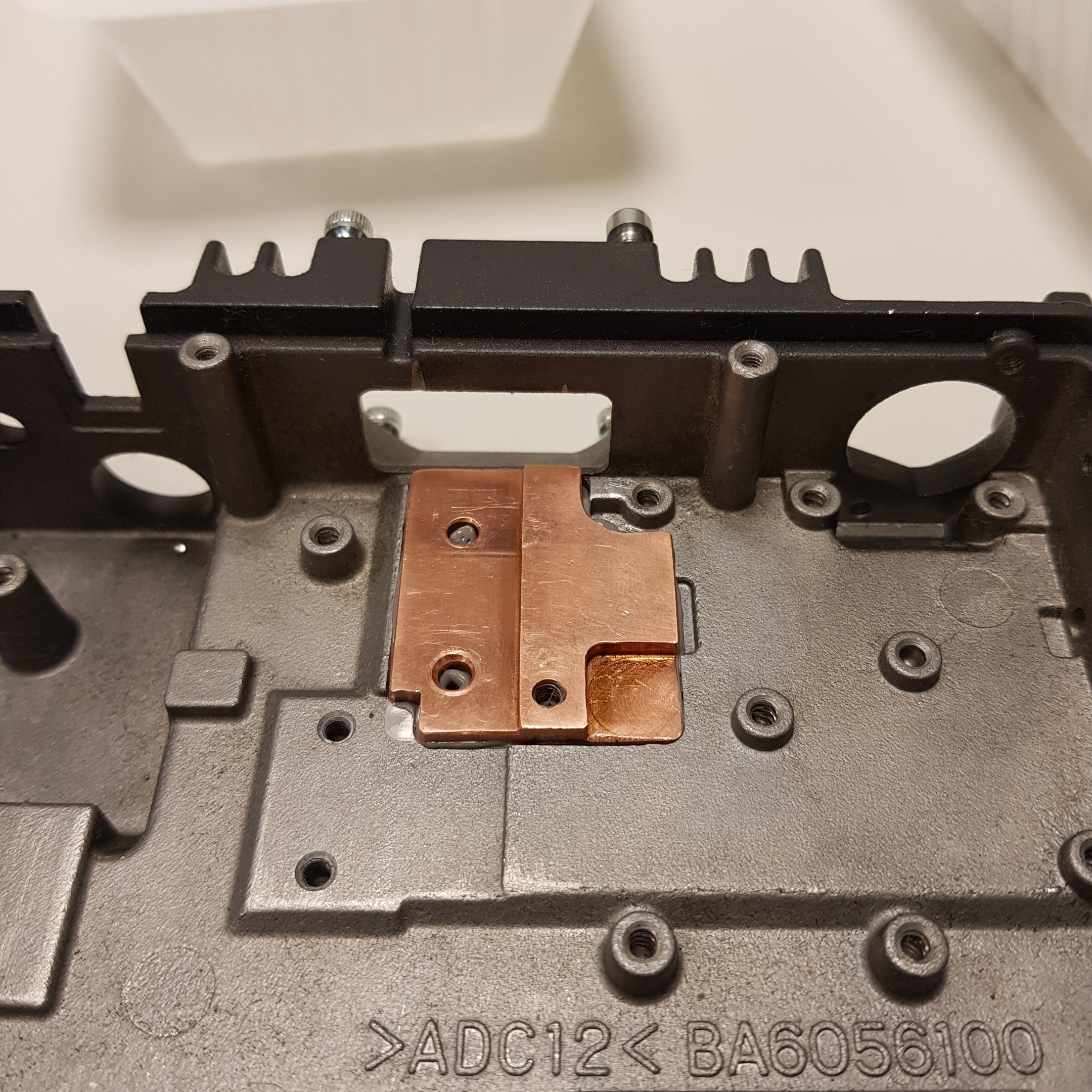
With modern fets (both LDMOS and ordinary MOSFETS) a considerable amount of energy is converted on a relatively small dye (the slice of silicon). The junction temperature, that is the temperature that the silicon of the fet can reach, is by definition somewhat higher then the temperature that the fet case can reach, but is bound to a maximum to keep the fet in a healthy shape. It is therefore important that the generated heat by the fet is distributed in an optimal manner towards the cooling chassis. Older fets, which were larger and could not reach the enormous performances that we see today, were placed directly on an aluminum cooling profile, usually with a little heat conduction paste. With modern fets such as the RD70-HUF2, the surface of the fet is rather small and therefore requires efficient heat distribution. For this reason, the use of a copper heatspreader is rather common nowadays. The heat conduction coefficient of copper is almost twice as high as Aluminum. Now copper is precious. Generally, cooling systems therefore consist of a small copper block to quickly distribute the direct heat of the fet. This copper block, with a surface that is considerably larger than the fet itself, is further mounted on an aluminum cooling block. In this way the fet can transfer its heat without reaching a critical temperature. The original FTM400/DR-1x copper strip within the power amp meets the exact size of the fet and therefore does not help to spread heat away from the critical zone.
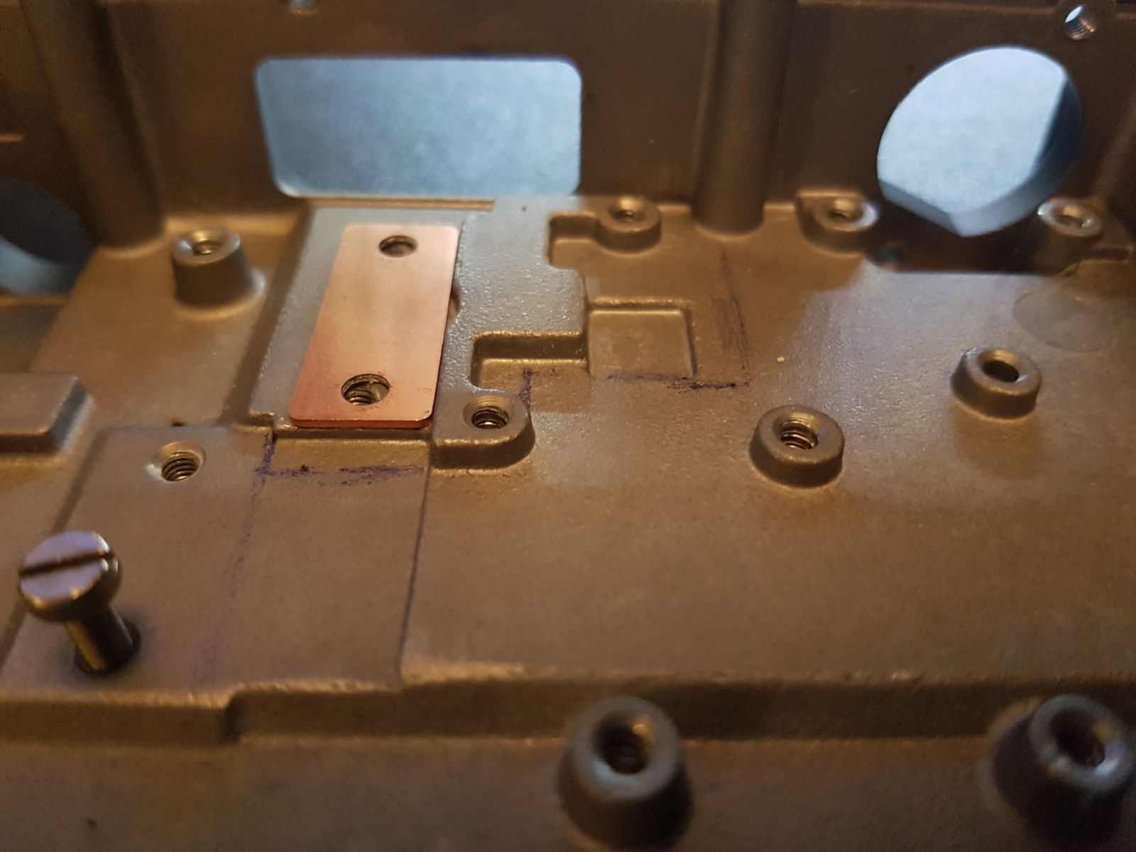
Copper plate exactly fits the FET size.
If we take a look at the FTM400 / DR-1x, a few things immediately become apparent:
- A strip of copper is indeed used, however, it is the same size as the fet.
- The die-cast aluminum chassis is not very smooth on the spot where the fet is mounted, but a bit rough.
In fact, the copper strip brings no added value, because it is placed between the fet and the aluminum chassis, causing two potential thermal resistance points rather then one, namely on both sides of the copper. This is not negligible; Some positive effects can be obtained by using heat conduction paste, but this only improves the situation a minor percentage.
The RD70-HUF2 fet has a thermal resistance between the dye and the housing (Rth-J-C / Resistance Thermal from Junction to Case) of 0.5 degree per Watt. In other words, with every Watt that is converted into heat, the temperature of the silicon rises by half a degree. With an ideal cooling (which is never reachable) the temperature of the fet in our example from above increases by about 32.5 degrees. Unfortunately, we have come to the conclusion that the fet has become so hot that the soldering lips on the drain (the output) have risen above the melting point of the soldering temperature, so at least more than about 227 degrees C, which is significant. This took us to the conclusion that the cooling system is far from optimal.
Modifying
How can this be improved? Repairing the set and putting it back into operation the same way as before is not an option, especially for a repeater. That’s why we have made three changes:
- Applying a better copper heatspreader to lower the temperature of the fet.
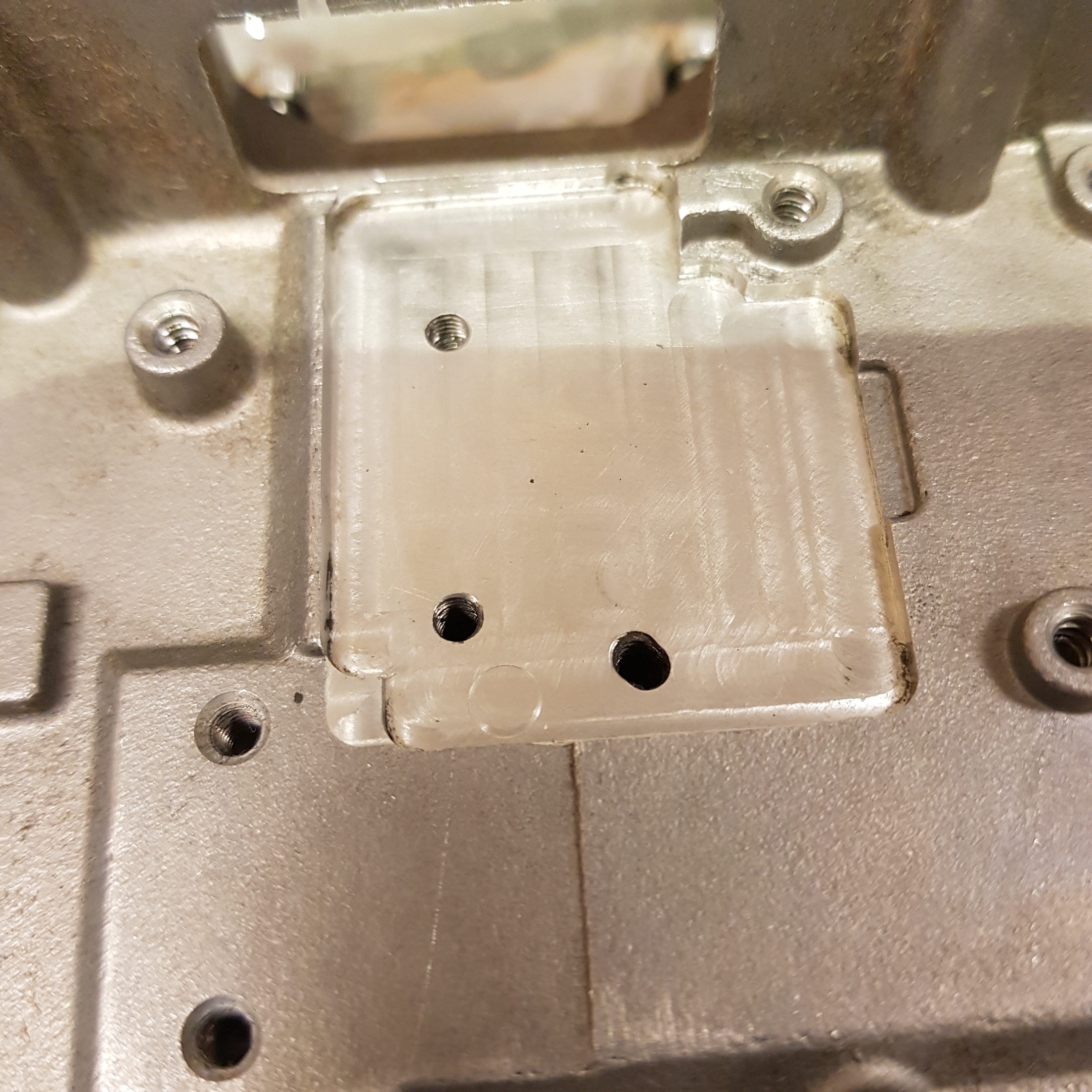
- Smooth polishing or milling of the chassis for optimum contact surface with the copper.
- Optimizing the airflow.
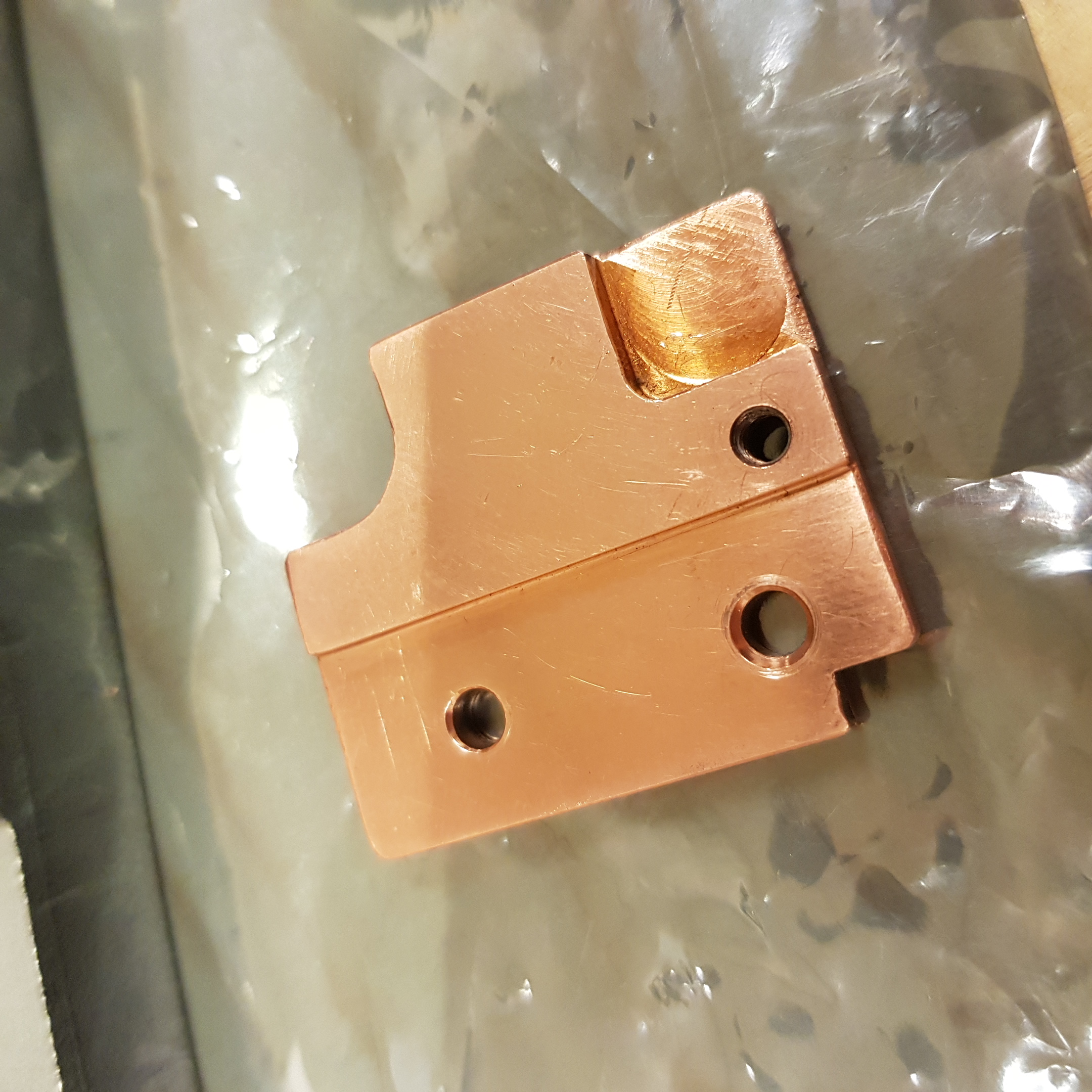
The new heatspreader, about 2,5x the original one
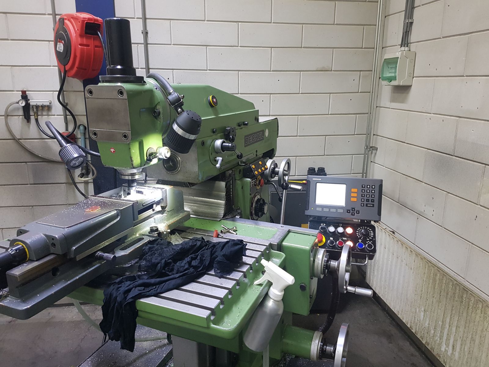
Resolving point 1 and 2 have been the biggest challenge. When you look at the chassis you immediately notice that it is designed in such a way that the various surfaces are at different levels. This makes it difficult to construct an alternative piece in copper. In addition, the space for such a block is very limited because there are electronic parts at the bottom of the PCB as well. After some fitting and measuring we came to the insight that a heatspreader could be made that was about 2.5x the surface of the fet. This is still not ideal but a quick calculation shows that the junction temperature of the fet will be reduced by about 40 … 45 degrees, which is very worthwhile. The heatspreader has been engineered and milled by René (PE9RX) who appeared to be very creative on the mill. The bottom of the copper is completely flat, implying that the chassis also needs to be modified. For this purpose a flat milling cutter is used with which a smooth surface is created ensuring that the copper block perfectly fits.
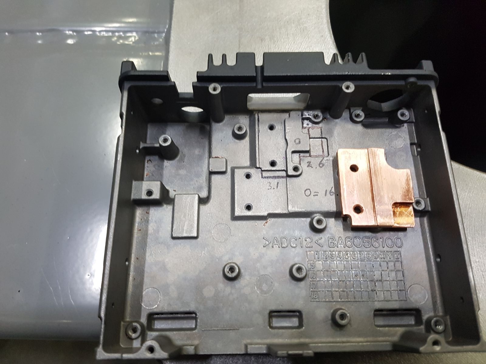
The new fet in place
An additional advantage of the applied heatspreader is that it also brings good contact with the PCB on the side of the drain. In the first photo from this article you can see that this part of the PCB can develop a very high temperature. The chassis modification already fixes this, but due to this extra cooling surface the temperature remains significantly better within the limits.
Then the third point, the airflow. In doing so, we noticed something strange when re-installing the repeater: At PI1NOS we utilize a power source from Delta Electronics, a well-known high performance supplier from the Netherlands. The power supply used provides 12 volts maximum with sufficient current. When switching on the repeater, it immediately became apparent that the chassis fan placed in the back of the repeater did not rotate. Until then, we were under the impression that this fan was always working at a constant speed. We therefore put the repeater on the test bench again and noticed that at about 12.2 Volt there was suddenly movement in the fan. Some experiments indicated a rather inexplicable behavior of the fan; sometimes it runs fast and sometimes slowly without a reproducible reason. We have taken care of this by using another (also a Delta) supply unit that does deliver the ordinary 13.8Volt.
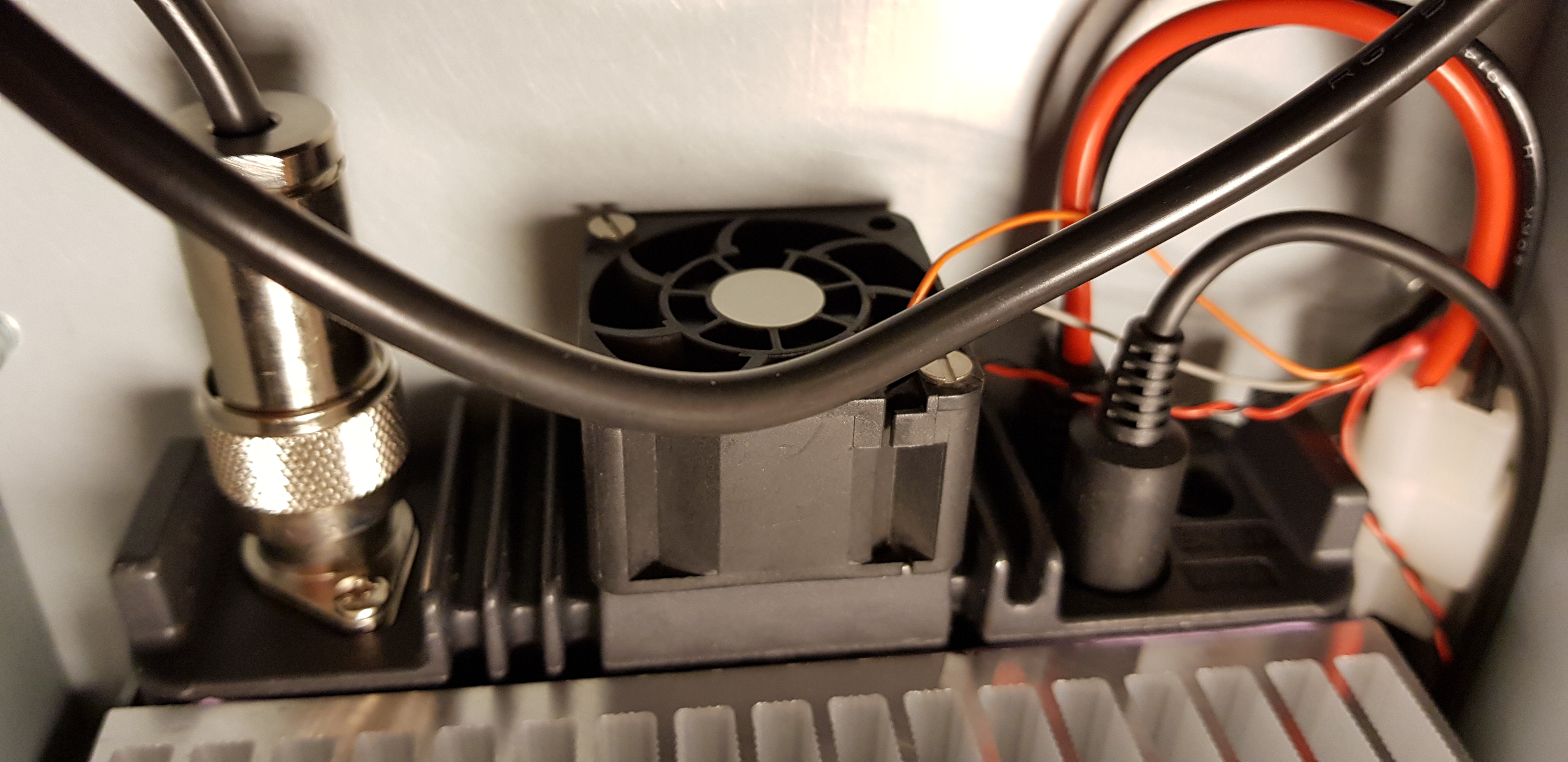
An extra high performance fan…
A second change we have made is reversing the airflow. Usually, principles of forced air cooling is based upon suction rather then blowing, but with this system we have learned that the power amp remains about 5 degrees cooler this way. In the original situation, air is sucked into the left side of the repeater, goes through the entire cabinet and further out through the transmittermodule via the rear, where the chassis fan is located. By reversing this, the cool air, without heating effects from other electronics, ends up directly at the transmitter. A second fan is placed on the other side of the transmitter, apparently with the intention to further increase the flow. Part of the air goes through the set to keep the PCB cool, even if this is only a small particle. We ourselves had our reservations about this, given the tunnel construction. With the original FTM400 a fan is placed on the back of the transceiver and also the DR-1x offers this possibility because the chassis is the same. The difference is that the DR-1x does not use such a fan. We ourselves had the desire to blow a reasonable amount of air through the set and not just over the outer cooling. Therefore it was decided to place a third fan that can be found on the back of the chassis. Now there was by coincidence a very powerful fan available that is normally used in (1HE) servers. These are usually two fans running in the opposite direction for even more cooling, but in the DR-1x we have divided these in two because even more wind did not seem necessary. This fan ensures that the inner transmitter remains reasonably cool, which extends its life dramatically.
Testing and practice
A first test showed that the transmitter operates in accordance with specifications. The powers in L / M / H mode were neatly 5, 25 and 50 Watts. First tests were done with an infrared temperature gauge without applying any further forced cooling. After all, we wanted to know if the heat of the fet was neatly transferred to the chassis. In the past, the temperature of the bare chassis did not go beyond 45 degrees, which, of course, is out of order in view of the dissipated energy. After about 3 minutes of transmitting, the temperature of the bare cooling block had risen to 67 degrees, a considerable increase with respect to the original situation. Unfortunately we lack the thematic specifications of the chassis and with the extra cooling profile it is even more difficult to get an idea. Fact: with the addition of the extra profile the temperature remains 8 degrees lower in an unrestrained state.
Finally, the repeater has been reconstructed and the forced cooling is put back into use, including the extra fan. By the way, the chassis fan normally always runs, but the internal fans are controlled from the transmitter by a certain temperature threshold. After about 20 seconds of transmitting, these fans switch on and, depending on the temperature reached near the fet, one continues for a certain amount of time. The good news is that we have come to the conclusion that the repeater has a significantly lower operating temperature at high power. If the drain temperature has exceeded 227 degrees in the past (which we learned from the strongly corroded drain solderings) infrared measurements now show that it does not exceed 68 degrees when using forced cooling. The temperature of the fet itself is more than 40 degrees lower than before.
Conclusion
 Well, we were not that crazy about the whole DR-1x and system fusion concept from Yaesu from the beginning. In the past we have had serious problems with the Wires-X software and DR-1x firmware and even in the current version (1.10Q) we are still encountering problems. This manifests mainly in local operation and is therefore fortunately of less importance. In addition PI1NOS suffered over a couple of months of system hookups after which a hard-reset was necessary. Fortunately, we can do this remotely by switchin off- and on the power supply
Then we have learned about the “burnt-out repeaters” as the first photo shows. The recommended modification of Yaesu is deemed to be only slightly successful. In any case, fortunately, we did not have an “inner fire”as some others have experienced. We now have to lean and see whether the modifications that we have applied will prove to be succesful over time. At Hobbyscoop we think that a repeater system, able to transmit with an output power of 50 Watts must actually be able to supply this 50 Watts, regardless of circumstances. The adjustments made will undoubtedly help, we hope this is sufficient.
A few more comments:
If you own an FTM400 or DR-1x and you do not have the desire to implement the abovementioned changes, use the set at 70cm preferably not above the mid power setting of 25 watts. At 2m the set is significantly more efficient and we do not know any examples of such problems at 2m.
The datasheet of the RD708-HUF2 also provided some interesting information: RD series RF power transistors are designed for consumer mobile communication terminals and were not specifically designed for use in other applications. In particular, while these products are highly reliable for their designed purpose, they are not manufactured under a quality assurance testing protocol. and fixed station applications that operate with long-term continuous transmission and higher on-off frequency during transmitting.
The text above shows that the RD-70HUF2 fet used in the DR-1x is actually less suitable for use in base stations and repeaters. We therefore ask ourselves what Yaesu had in mind when designing the DR-1x and her successor, the 2x. At Hobbyscoop there is a strong impression that these repeaters are nothing more then a cheap method to make the System Fusion application easily available, but it shows that no real measures have been taken to ensure the reliability that one may expect from a base station repeater, The “out of the box” performance is clearly below par.
PI1NOS is now back in the air and runs at the same power as before, namely 50 Watts (without filtering, cables, etc). We are very curious if the improvements we have made are sufficient to keep the repeater intact.
Update 12-2020:
Oh no! The DR-1x has failed again! After a good 2 years of intense operation (many hours of continuous transmission time per day) at full 50 Watts of output power, the LDMOS power fet has failed again! This was unexpected.
Within our foundation we have thoroughly discuss this returning problem. After all, we decided to repair the repeater again and limit its output power to 25Watts, incurring half of the dissipation in heat. It has to be said: The idea of Yaesu is nice, but the implementation and price level far below any quality standard that may be expected from this gear.